-
Click OK.
-
Before creating the Hole, right-click the board PartBody and select Define in Work Object so that the PartBody becomes the active product.
-
Select the board to define the working plane.
The Hole Definition dialog box appears.
CATIA previews the hole to be created with default parameters. -
Enter 4mm for the diameter and click OK.
The hole is created. -
Repeat the steps 5, 6 and 7 for the second hole.
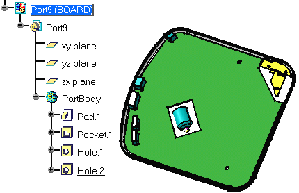
The pocket and holes are added to the specification tree. 
-
Right-click Hole.1 in the specification tree to display the contextual menu.
-
The Properties dialog box opens. 
-
Click More... .
-
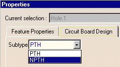
Select Circuit Board.
-
Switch the Subtype to NPTH (non conductive) and click OK.
The hole is more than a simple hole: it has a technological property. -
Repeat the steps 9 to 13 for the second hole.
These holes are used for mounting purposes.

