Pattern Usage During Import

This task shows you that the rectangular pattern used for mounting a component, is recognized during import.
This feature is available on both the board and manufacturing panel.
aprereq.gif (1223 bytes)

Before starting, set the Tools > Options > Infrastructure > Part as shown below:

  1. Open the Pattern.idf document from the samples directory.
    The Circuit Board Design Import dialog box opens.

  2. Click to activate the Catalog light.

  3. Browse to select the Pattern.catalog.
    The Catalog light becomes green.

  4. Click OK to validate.
    A message informs you that the catalog is unchanged (it is in read only mode).
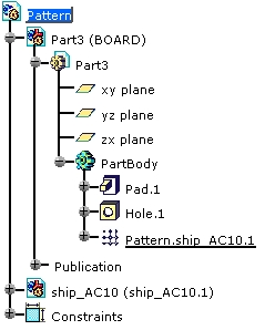
    The import result looks like this:

ainfo.gif (980 bytes) The idf file contains the board, the component and the holes. During the import, the holes coordinates are analyzed and recognized as defining a pattern. If you move or delete the component, the pattern will be updated (see the next task).