Patterns are often used for mounting purpose.
-
Select the Hole button
 to create the hole to be patterned.

-
Select the hole to pattern.
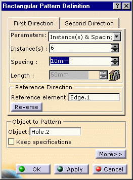
The Rectangular Pattern Definition dialog box opens.
-
Enter the following values for the first direction:
- Instances: 6
- Spacing: 10mm
- Reference Direction: select the bottom edge (Edge.1)
-
Reverse the direction.
-
Enter the following values for the second direction:
- Instances: 2
- Spacing: 20mm
- Reference Direction: select the left edge (Edge.2)
-
Click OK to validate.
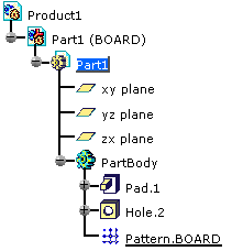
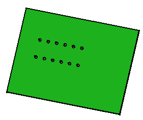
The pattern is added to the specification tree and the result looks like this: 
