|
This task shows you how to create a
constraint area. |
 |
A
constraint area is a space reservation used for different purposes such
as allowing/forbidding the routing or placing of components etc.
This feature is available on both the board and the
manufacturing panel. |
 |
Open a CATProduct document, containing a board. |
 |
-
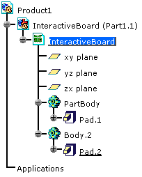
Choose the Insert > Body menu item (optional).
Body.2 is created, belonging to the interactive board
component.
-
Select Sketcher
 . .
-
Select the board to define the working plane.
-
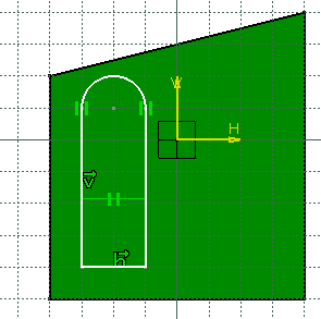
Click Profile
 and draw the contour of the constraint area.
-
Click Exit
Sketcher
 to return to the 3D world.
-
Click Pad
 . .
The Pad Definition dialog box appears.
-
Enter 5mm in Length.
-
Click OK to validate.
-
Select
Create Constraint Area
 . .
| The Constraint Areas dialog box
opens. |
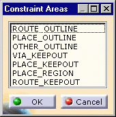 |
| The constraint area types are: |
-
Route outline: an area where routing electrical connections
is allowed
-
Place outline: an area where component placing is allowed
-
Other outline: other area type defined by an outline, cutouts
and a thickness
-
Via keepout: an area where via placing is forbidden
-
Place keepout: a mechanical space reservation where the
component height is limited
-
Place region: an area where placing is limited to component
of certain types
-
Route keepout: an area where routing electrical connections
is forbidden
|
-
Choose PLACE_KEEPOUT and click OK.
The place keepout area is displayed in transparency.
The pad is more than a simple pad: it has technological
properties.
|
|
|
When you create a constraint area interactively, the body
is not automatically renamed with the constraint area type (as it
works on import). However, you can change its name using the Properties
contextual menu. |