-
Select a component.
-
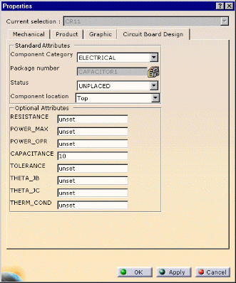
Using the right mouse button, open the Properties dialog box.
-
Click the More... button then select the Circuit Board Design tab.
In this example, the component is located on the Top face and its Status is Unplaced. 
-
You can change the Component Status to Placed.
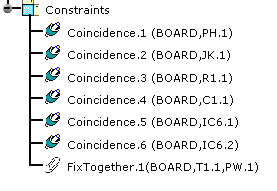
A placement constraint is created. Using Assembly capabilities, you can edit this constraint. 
You can change the offset value.
The offset value is taken into account when you export the data in IDF 3.0.You can still move the component to the desired location on the surface of the board.
-
You can change the Status to Fixed.
The FixTogether Constraint is created between the board and the component. 
-
Other properties come up with IDF 3.0 file support such as:
Optional Attributes: - Capacitance
- Resistance
- Tolerance
- etc.
as well as user-defined attributes (optional). They can be valuated in this dialog box.
-
Click OK to validate.