-
Open an idf file containing holes.
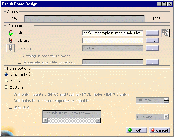
The Circuit Board Design Import window opens.
The different holes options are: - Draw only: the holes are not drilled but the contour is displayed in the geometry (default option)
- Drill all: the holes are drilled.
- Custom:
- Drill only mounting (MNTG) and tooling (TLG) holes: only mounting and tooling holes are drilled, other holes are displayed.
- Diameter limit: drills the holes which diameter is superior to the given value.
- User rule: gives access to the rule editor.
To know how to write a rule, refer to CATIA - Knowledge Advisor User's Guide
-
Select the option of interest, in our case: Draw only.
-
Click OK to validate.
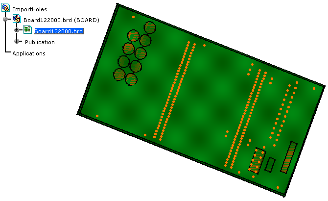
The import is performed and the result looks like this: 