-
Right-click the root product and select Components
> Board in this one.
-
Right-click the root product again and select
Components > New Product
 .
.
Name it Mechanical: you will use this one to create the
context: the casing.
-
Right-click the Mechanical product and
select Components > Existing Component
 .
.
The File Selection dialog box opens.
-
Select the casing.CATPart.
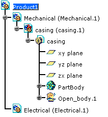
| At this stage, the document looks like this: |
 |
-
Double-click the Electrical product and
select Start > Equipment & Systems > Circuit board Design
workbench.
-
Select
Import in Context
 .
.
You are prompted to select a face as the context.
-
Select the top face of the casing.
The Import dialog box opens.
-
Navigate to select the Reconciliation1.idf
file.
-
Navigate to select the default.lib file then
click OK.
The status bar indicates the import progression.
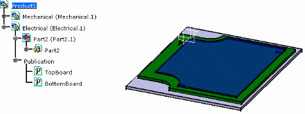
The result looks like this:
Note: click the Publication in the
specification tree.
It shows the association of labels to the geometrical faces of
the board: Top and Bottom. |
 |
-
Switch to the Assembly workbench.
You will define the label for the casing top face.
-
Select Tools > Publication Management
 .
.
The dialog box opens.
-
Click Add... .
The Publication Definitions dialog box opens.
-
Enter a value in the name field for example: top
casing.
-
Select the casing top face.
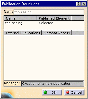
| The dialog box looks like this: |
 |
-
Click OK to validate.
-
Double-click to activate the root product.
-
Select
Coincidence Constraint
 .
.
|
You are prompted to select the faces you want to
be constrained:
- select the publication label of the top casing (top
casing)
- then the publication label of the bottom of the board (BottomBoard)
|
| The coincidence constraint is created and the Constraint
Properties dialog box opens: |
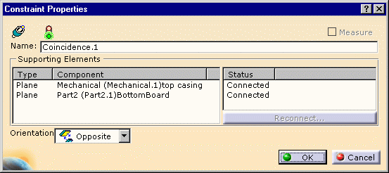 |
It shows the t type, components and status of the constrain.
Click OK to validate. |
-
Right-click the Electrical Product and
select Components > Replace Component
 .
.
The File Selection dialog box opens.
-
Select the Reconciliation2.idf file.
In this file a pocket has been added to the board.
The Import dialog box opens to let you choose the
default.lib
The status bar indicates the progression.
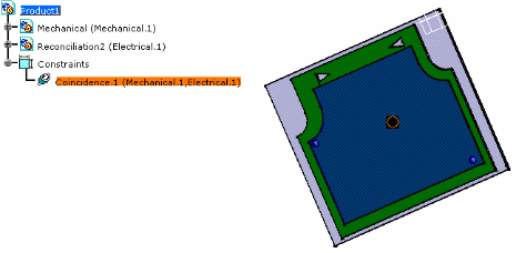
The result looks like this: |
 |
-
Double-click Constraint
 .
.
You can see the Constraint Definition.
The coincidence constraint has been maintained although the board
has been replaced. |
 |
-
Click OK to validate.
![]()