- reset the position of the compass (and selected object) via its manipulation handle (red square), by specifying its X, Y and Z coordinates and rotation coordinates with respect to the center of the 3D scene
- translate the object (or just the compass) to a new position in increments along the X, Y and Z axes
- rotating the object (or just the compass) about the X, Y and Z axes in increments
- translate over a specified distance in the direction of the privileged plane
- translate over the distance between two elements (line/edge/plane) you select
- rotate through an angle you set, or an angle between two elements (line/edge/plane) you select.
Open the document Manipulators.CATProduct.
-
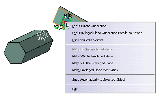
Drag and drop the compass onto the object, then point to the compass and right-click to display the 3D compass, or double-click the compass to display the contextual menu.
In our example, drag and drop the compass onto the object and right-click: 
-
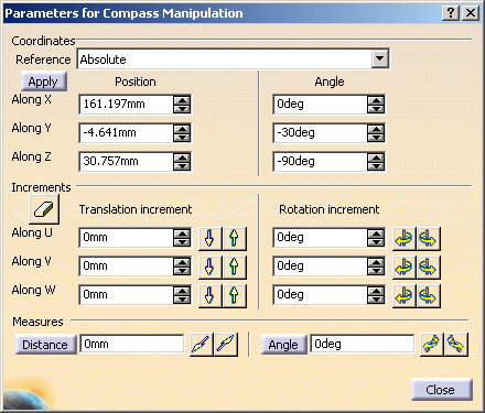
Right-click then select Edit to display the Parameters for Compass Manipulation dialog box:


The Parameters for Compass Manipulation dialog box stays open during manipulation. Note that: - the current coordinates of the compass manipulation handle (red square), with respect to the center of the 3D scene, are displayed in the corresponding fields for the Position option. In our example, the center of the 3D scene, in this case, is the point of intersection of the 3 planes located on the pad
- when the compass is snapped onto an object (whether the
Parameters for Compass Manipulation dialog box is open or
not), the letters identifying the compass axes are displayed
differently from the usual color and size: they are white
surrounded with a dark-blue border and their size is 50% bigger for
greater readibility whatever the background color.
This enables you to see more clearly the compass orientation, which is especially useful when the compass is snapped onto objects with many different colors or with many small details.
-
In the Coordinates area, select the axis system with respect to which you will edit the coordinates of the compass. You can select:
-
either the Absolute axis system: allows you to move the part with respect to the absolute axis system of the product containing the part
-
or the Active object: allows you to move the part with respect to the object which is active. To define an object as being "active", double-click it in the specification tree: the object is then highlighted in blue to indicate it is active.
For instance, let's suppose the active object is a part with a local axis system defined as current: in that case, choosing Active results in displaying the coordinates of the compass with respect to the local axis system of the part.
-
-
Reset the X, Y and Z coordinates of the compass to zero, using the Position options, then click Apply.
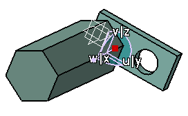
In our example, because you dropped the compass onto an object, the compass and the object patch are moved to the center of the 3D scene as follows: 
The Increment options let you translate or rotate the compass about the U, V and W axes in increments. When using these options, axes are highlighted according to the increment button you click as shown below: 

Translation along U
Rotation about U 

Translation along V
Rotation about V


Translation along W Rotation about W Once an axis is highlighted, it remains so until: - you highlight another axis by clicking it with the mouse
- you move the compass to another location using any interaction other than a click on one of the increment buttons
- you close the Parameters for Compass Manipulation dialog box.

Increment options can be used in the Part Design workbench but note that axes are not highlighted. -
To translate the compass and the object by increments along an individual axis (U, V or W), set the translation values for an axis, then click
 or
or
 to translate in forward or reverse direction, respectively.
 -
To translate an object along a vector derived from two objects you select, click Distance in the Measures area and select the two elements.
When you click Distance, all options in the dialog box are grayed out. You can select any of the following:
- a point
- a line
- or a plane.
The value for the detected distance is highlighted in the appropriate fields, expressed in the units of the compass. Note that, depending on the compass orientation, some or all of the X, Y and Z coordinates might be calculated.
If the first element is a line or a plane, you can then select a second element or enter a distance. For example, selecting a line implies that you want to translate the object in the direction of the line, and you can enter the distance for the translation in the Distance field. However, if you just select the two elements, the distance between the two is displayed in the Distance field, and the object will be translated over this distance and in the same direction. If the second element is a plane, the direction of translation is normal to the plane.
Then, click either
 or
or
 to the
right of the Distance box to translate the object in the
reverse or forward direction, respectively.
 -
To rotate, set the rotation angle and click
 or
or
 for the axis about which you want to rotate.
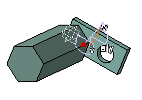
For example, with the object still located at the center of the 3D scene, rotating about the U axis produces this result: 
-
To rotate the object through the angle between two elements, click Angle and select the two elements.
You can select a line or a plane. The angle value is displayed in the Angle box.
If the rotation axis is parallel to one of the compass axes, the value is also displayed in the appropriate box in the Rotation increment area, the 2 other ones being reset to 0.Then click
 or
or  to
rotate the compass and the object about the computed rotation axis.
Note: the values you enter in the Rotation increments area and in the Measures area have no impact on each other. For instance, if you enter an increment value in the Along U box then click  ,
the increment you entered will not be taken into account. The
Rotation increments values let you rotate the object about an axis
and the Angle box in the Measures area lets you specify
a rotation angle between two elements you select.
Bear in mind that you can reset entered increments at any time simply by clicking
.
Once the compass is snapped to the object, you can drag its arcs to translate or rotate the object according to the increments you entered in the dialog box. When the dialog box is closed, the increments are kept for the compass and bounding box motions.
When you wish to reset the compass and move it freely according to one direction, access the Parameters for Compass Manipulation dialog box and set the corresponding value to 0.
![]()