| |
For an optimized accuracy, you
need to store your screen dimensions (in millimeters), in the
following two variables:
set CATWidthMMOfScreen = width_in_millimeters
(on Windows)
or
export CATWidthMMOfScreen = width_in_millimeters
(on UNIX)set CATHeightMMOfScreen = height_in_millimeters
(on Windows)
or
export CATHeightMMOfScreen = height_in_millimeters
(on UNIX)
Otherwise, the measured dimensions may vary depending on the
operating system. You have to do these measurements by yourself
using a tape measure. The screen dimensions correspond to the horizontal
measurement followed by the vertical measurement.
If your computer does not use the full screen for display (e.g. if there
is a strip on the left side and right side of your screen), you have to
measure only the part of the screen used for display. |
 |
-
Select View > Render Style > Perspective or
View > Render Style > Parallel to display the object in a
perspective or parallel view, respectively.
|
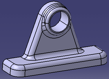
In our example, the object is displayed in
Parallel view: |
 |
| Perspective is related to the size of
the object being viewed and the distance from the object to the
observer. |
-
In the
power input box, key in the following command:
c:Scale Planesthen
press Enter. |
 |
This command is
also accessible via the Commands tab of the
Customize dialog box.
For more information on customizing commands, refer to
Customizing Command Properties in
this guide. |
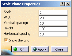
| The Scale Plane Properties
dialog box opens: |
 |
-
Click Apply to display the plane and
keep the Scale Plane Properties dialog box:
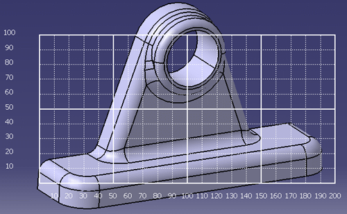 |
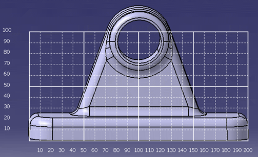
| As shown in the picture, the plane is
represented by a transparent grid which lets you visualize the
object displayed behind. |
| This grid is
divided into squares and the space between these squares as well
as the width and height (in millimeters) correspond to the values
displayed in the Scale Plane Properties dialog box.
In our example, the width is 200 mm and the height is 100 mm.
In the picture above, you can see that:
- the width is divided into 20 squares, each of them being
equal to 10 mm (as indicated in the Vertical spacing
box)
- the height is divided into 10 squares of 10 mm each (as
indicated in the Horizontal spacing box).
If you set the space between vertical and horizontal lines to
"20 mm", the grid looks like this: |
 |
| The width is now divided into 10 squares of 20 mm
each and the height into 5 squares of 20 mm each. |
-
In the Scale Plane Properties dialog box,
key in a Scale value.
| The default value ("1") provides a real size display whereas
"0.5" corresponds to a halfsize display. You can thus measure
small objects by entering a scale factor greater than 1 as well
as big objects by entering a scale factor lower than 1. |
-
Set the plane Width and Height
in millimeters. In our example, we keep the default values.
-
Set the space between vertical and horizontal by
entering a value (in millimeters) in the Vertical spacing
and Horizontal spacing boxes, respectively.
|
In our example, we keep the default values.
If the value you enter is not a multiple of the
value set for Width or Height, the space
between squares are approximated to give a round number (and this
may make it more difficult to measure directly on screen). |
|
|
The
Show the grid check box lets you activate or
deactivate the grid display.
It is recommended to display the grid when you are working in a
conical projection. |
-
Click OK (or Apply then OK)
to validate and close the dialog box.
-
Adjust the viewpoint so that the object is correctly
snapped on the grid. To do so, follow the instructions below according
to the view you selected:
|
|
|
|
|
The zoom mode is
locked when the Scale Planes command is running. By
"locked", we mean that zooming has an impact on the grid
position only and not on the display scale in order to let you
translate the grid on the model along its depth and measure the
model.
Note also that if the grid is far from the model, then the grid
disappears because measuring a dimension without the model does
not make sense. |
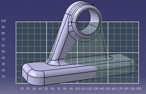
- if you are working in a perspective view (i.e. conical
projection), zoom progressively until the object is displayed
in front of the grid then translate the object as necessary to
align it with the grid and facilitate the measurement:
|
|
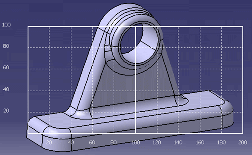
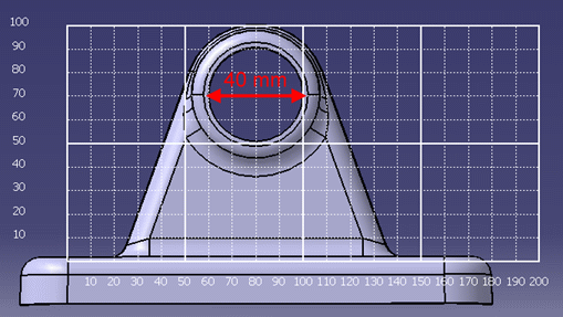
Let`s
have a look at our model which has been correctly positioned.
We are now able to measure the hole diameter and we see that the
size is comprised between 60 and 100 mm:100 mm - 60 mm =
40 mm
We can also count the number of squares:
4 squares of 10mm each = 4 x 10 = 40 mm
according to the values defined in steps 3 to 5. |
 |
|
|
Translating or
zooming the object does not affect the grid size since its
dimensions are defined in the Scale Plane Properties
dialog box. |
-
To exit the command, click Close in the
Scale Plane Properties dialog box.
|
You can also key in c:Scale Planes
once again in the power input box. |
|