
|
This task shows you how
to remove a body from two parts in assembly context. |
 |
Open the AssemblyRemove_Add.CATProduct
document. |

|
1.
|
Click the Remove icon:
 |
|
2. |
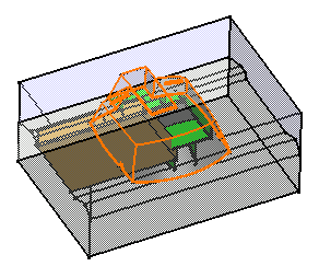
Select Body.1 from MoldedPart as the body to be removed. |
|
|
 |
|
3. |
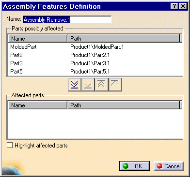
The dialog box that appears displays the names as well as
the paths of the parts that may be affected by the removal. |
| |
|
The assembly feature's
name now appears in the top left corner of the dialog box. If desired, you
can edit this name. |
|
|
 s s |
|
|
The frame 'Affected
parts' is exclusively reserved for the parts you wish to use. For the
purposes of our scenario, you are going to remove material from Part2 and
Part3.
Move these parts to the list 'Affected parts". To do so, select Part2
and click the
 button.
Repeat the operation for Part3. Alternatively, double-click each part. button.
Repeat the operation for Part3. Alternatively, double-click each part.
The other three buttons lets you move the names of the parts from one
list to another too:
| |
 moves all selected parts to the list 'Affected parts'
 |
|
| |
 moves all selected parts to the list 'Parts possibly affected'
 |
|
| |
 moves the selected part to the list 'Parts possibly affected'
 |
|
|
 |
|
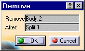
The Remove dialog box that has
appeared, indicates the part to be removed. |
 |
 |
4. |
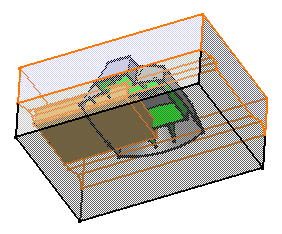
Check the option Highlight affected
parts to clearly identify the parts affected by the operation. |
|
|
 |
|
5. |
Click OK to confirm.
Material is removed from Part 2 and Part3. |
|
6. |
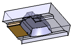
To better visualize the result, put
Part 5 and Body.5 in no show mode. You can see the portion of material that
has been removed. |
|
|
 |
|
|
A new entity 'Assembly Features'
appears in the specification tree. It contains the assembly removal
referred to as 'Assembly Remove.1" and the name of affected parts.
Moreover, this feature has generated a remove feature in Part2 and a
remove feature in Part 3. An arrow symbol identifies these removals
 in the tree,
meaning that a link exists between Assembly Remove.1and them. in the tree,
meaning that a link exists between Assembly Remove.1and them. |
|
|
 |
|
|
Editing an Assembly Remove
|
|
|
To edit an assembly remove
operation, double-click 'Assembly Remove.X' entity. You can then modify the
list of the parts possibly affected by the removal. |
| |
|
Reusing Part Design Remove Features
|
| |
|
To increase your productivity, you
can create Assembly Remove Features from existing Part Design Remove
features, or more precisely by reusing the specifications you entered for
designing Part Design remove features. To do so, just proceed as follows: |
| |
1.
|
Click the Remove
icon
 . . |
| |
2. |
Select the Part Design
Remove feature of interest. |
| |
3. |
Both the Remove
Definition and the Assembly Features Definition dialog boxes display. You
then just need to specify the parts of interest.
The assembly remove feature inherits the specifications as displayed in
the Part Design Remove Definition dialog box. You can edit these
specifications at any time. Editing an Assembly feature created in this way
does not affect the specifications used for the Part Design feature. |
| |
|
Reusing Assembly Design Remove Features
|
| |
|
The application also lets you
reuse Assembly Remove Features' specifications to accelerate the design
process. In this case, you just need to select the existing assembly remove
feature, click the Assembly remove icon and then select a face. Only the
Assembly Features Definition dialog box appears to let you determine the
parts of interest. |
| |

 s
s![]() button.
Repeat the operation for Part3. Alternatively, double-click each part.
button.
Repeat the operation for Part3. Alternatively, double-click each part.


![]() in the tree,
meaning that a link exists between Assembly Remove.1and them.
in the tree,
meaning that a link exists between Assembly Remove.1and them.