-
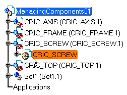
Click on the + sign to the left of the CRIC_SCREW (CRIC_SCREW.1) component in the specification tree.
The CATProduct is identified by the Product document icon.
Do not mistake the Product document (CATProduct)
for the Part document (CATPart).
The CATPart is identified by the Part Design document icon.
If the Product document containing the Part document is set to
Visualization Mode, editing the Part document switch automatically the
Product document to Design Mode. This is not an Assembly Design
behavior because the Design Mode is the only mode for Part
document.

The Part Design workbench is displayed.
-
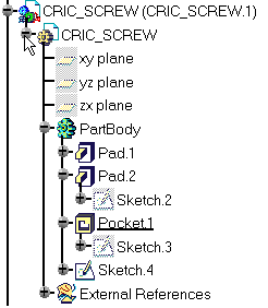
Click on the + sign to the left of Part Body.
-
Double-click the feature you need to edit. For example, double-click on Pad2 to display the Pad Definition dialog box. You can then enter the parameters of your choice.
For information about Part Design and the Sketcher, please refer to Part Design User's Guide and Dynamic Sketcher User's Guide respectively.
-
Once you have edited the part, double-click on ManagingComponents01 to return into Assembly Design workbench. The specification tree remains unchanged.
-
Double-click on the part CRIC_SCREW to open Part Design workbench again.
-
Select any circular face of CRIC_BRANCH1 and enter the Sketcher workbench.
-
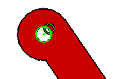
Create a circle and set a coincidence constraint for example:

-
Exit from the Sketcher and double-click on ManagingComponents01 to return into Assembly Design workbench.
Assembly Design workbench is then displayed and a
green wheel is added to CRIC_SCREW in the tree to
represent the contextual nature of the component:
![]() .
.
Note however that this symbol is displayed only if the option Keep link with
selected object is selected. For more information, please refer to Part
Design User's Guide.
