Open the CharacteristicCurves1.CATPart document.
Make sure you have an appropriate Generative Drafting license. For more information about this workbench, refer to Generative Drafting User's Guide.
![]()
-
Click
 or select File -> New...
 -
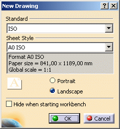
Select the Drawing type and click OK. The New Drawing dialog box is displayed.

-
Click OK.
-
The drawing sheet appears.
-
Tile the windows horizontally using the Window -> Tile Horizontally menu item.
-
Click Unfolded View
 in the Projections toolbar from the Generative Drafting
workbench.

This icon is active in the Projections toolbar provided you have an Aerospace Sheetmetal Design licence.
-
Choose the zx plane in the Sheet Metal specification tree. A preview of the view is displayed in the drawing.
About characteristic curves
Administrators can customize characteristic curves through standards:
- graphic properties (color, line type, thickness) apply to both 3D views (in the Aerospace SheetMetal Design workbench) and 2D views (in the Generative Drafting workbench).
- visibility specifies whether characteristic curves should be represented in 2D views.
Refer to the Administration Tasks chapter for more information on this subject.
