Locating instances consists in specifying anchor points. These points are sketches.
- cutouts
- holes
- beads
- flanges
- flanged holes
- stamps (except stiffening ribs)
- Aerospace Sheetmetal Design patterns
These features must lie on a unique and planar surface.
Open the UserPatterns1.CATPart document.
-
Select the feature to be duplicated.
Here we selected the cutout. -
Click User Pattern
 .
.The User Pattern Definition dialog box is displayed. 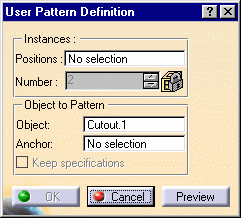
-
Select 'Sketch 3' in the specification tree and click Preview.
The sketch contains the points you need to locate the duplicated cutouts. 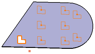

By default, the application positions each instance with respect to the center of gravity of the element to be duplicated. To change this position, use the anchor field: click the anchor field and select a vertex or a point. -
Click inside the Anchor field and select the point (Point.1) to indicate a new reference location.
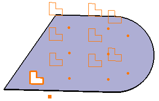
-
You can then click the points corresponding to the pattern instances to be removed.

Patterns should not go beyond the surface (this can be checked using the preview). 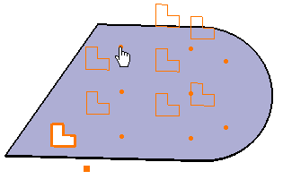
-
Click OK in the User Pattern Definition dialog box.
Cutouts are created at the points of the sketch. 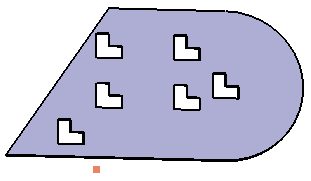

Would you need to unfold the part using Fold/Unfold  , you would notice that the pattern is updated.
- When you duplicate a pattern of flange, the edge of the flange spine and its instances have to be tangent to the wall edge: you cannot choose a direction of patterning not parallel to the flange spine.
- All instances of the flange pattern must lie on the same face as the flange pattern.
![]()