Creating Rectangular Patterns

In this task, you are going to create rectangular cutouts according to a pattern.
These features make the creation process easier.
You can only duplicate the following items:
  • cutouts
  • holes
  • beads
  • flanges
  • flanged holes
  • stamps (except stiffening ribs)
  • Aerospace Sheetmetal Design patterns

These features must lie on a unique and planar surface.


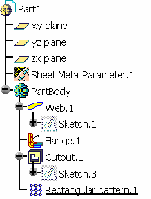
Open the RectangularPattern1.CATPart document.
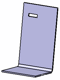
  1. Select the rectangular cutout you want to duplicate.
  2. Click Rectangular Pattern .

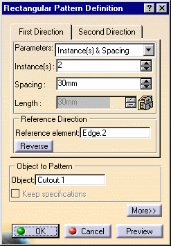
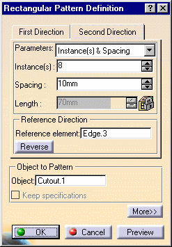
    The Rectangular Pattern Definition dialog box is displayed. Each tab is dedicated to a direction to define the location of the duplicated feature.
  3. Set the specification for the First Direction by selecting the first edge (Edge.2) as shown, to specify the first direction of creation.

    An arrow is displayed on the flange.

    The Reverse button enables to modify the direction.
    You can also click the arrow in the 3D geometry.

  4. Keep the Instances & Spacing options to define the parameters.

    Choosing these parameters types dims the Length field because the application no longer needs this specification to space the instances.
     
     
    You can set the duplication parameters by choosing the number of instances, the spacing between instances, or the total length of the zone filled with instances.
    Three options are available:
    • Instances & Length: the spacing between instances is automatically computed based on the number of instances and the specified total length

    • Instances & Spacing: the total length is automatically computed based on the number of instances and the specified spacing value

    • Spacing & Length: the number of instances is automatically computed to fit the other two parameters.

    For each of these cases only two fields are active, allowing you to define the correct value.

    If you set Instances & Length or Spacing & Length parameters, note that you cannot define the length by using formulas.

    Patterns should not go beyond the surface (this can be checked using the preview).
  5. Enter 2 as the number of instances you wish to obtain in the first direction.

  6. Define the spacing along the grid: enter 30mm.

    Defining the spacing along the grid and the length of your choice, would make the application compute the number of possible instances and space them at equal distances.
  7. Now, click the Second Direction tab to define the other parameters.

    Note that defining a second direction is not compulsory. Creating a rectangular pattern defining only one direction is possible.
  8. Select the second edge (Edge.3), as shown, to define the second direction.

  9. Keep the Instances & Spacing option: enter 8 and 10 mm in the appropriate fields.

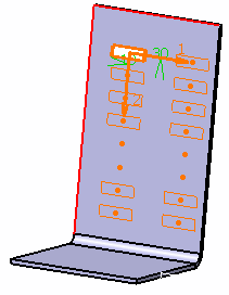
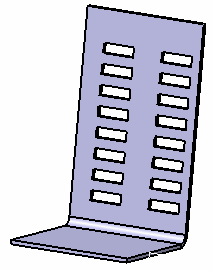
    Additional cutouts have been aligned along this second direction.
     
  10. Click OK to repeat the cutouts.

    After the update, the part looks like this:
     
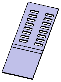
  11. Click Unfold .

    The pattern is updated on the unfolded view.
  12. Click the More>> button to display further options.

    The Simplified representation option lets you lighten the pattern geometry, when more than 10 instances are generated in one direction. What you need to do is just check the option, and click Preview. The system automatically simplifies the geometry.

    You can also specify the instances you do not want to see by double-clicking the dots. These instances are then represented in dashed lines during the pattern definition and then are no longer visible after validating the pattern creation. The specifications remain unchanged, whatever the number of instances you view. This option is particularly useful for patterns including a large number of instances.

     
    • When you duplicate a pattern of flange, the edge of the flange spine and its instances have to be tangent to the wall edge: you cannot choose a direction of patterning not parallel to the flange spine.
    • All instances of the flange pattern must lie on the same face as the flange pattern.