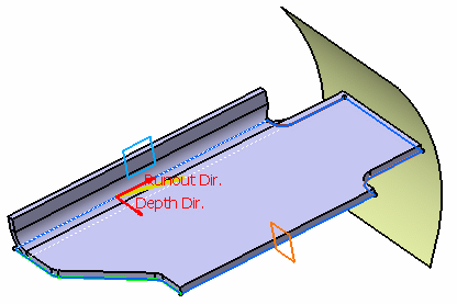
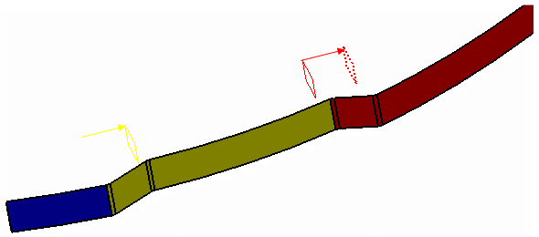
This task explains how to create a joggle. A joggle is a feature which causes the main feature, i.e. a surfacic flange or a web, to be locally deformed.
The joggle is a feature which cannot exist alone, it is always defined on a surfacic flange or a web.
Open the Joggle1.CATPart document.
-
Click Joggle
 .
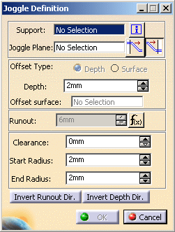
The Joggle definition dialog box is displayed.
-
Select the surfacic flange or the web as the support.

The Support of the joggle is not automatically set to the last created feature (surfacic flange or web). 
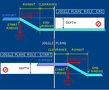
You can click  to display a schema showing the joggle parameters to be defined.
-
Choose a plane as the joggle plane, here we choose Plane3.
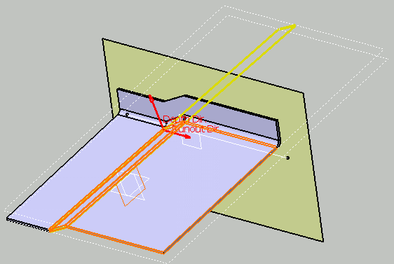
The blue curve defines the boundary of the web.
The yellow line is a preview of the joggle.
The vectors show you the joggle directions:
- The vector on the surfacic flange or the web support determines the depth direction
- The vector on the joggle plane determines the side on which the joggle is to be created
In case there are several intersections between the surfacic flange or the web and the plane, the closest intersection is chosen.
-
You can modify the following parameters of the joggle by clicking the up and down arrows.
depth: offset from the support surface (shown as dotted lines)
The dotted lines must remain inside the blue curve
runout: length of the offset, between the original surface of the surfacic flange or the web and the new surface (joggle)
clearance: length added to the offset at the joggle starting plane
start radius: fillet between the runout and the surfacic flange or the web
end radius: fillet between the runout and the offset.
-
Click OK.
The joggle (identified as Joggle.1) is created and the specification tree is updated accordingly.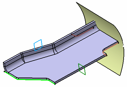

- If you modify the depth, the runout adjusts automatically,
thanks to the formula applied to the runout parameters. If you do
not want it to be adjusted automatically, right click on the runout
field, select Formula ->Deactivate in the contextual
menu.
If you want to have further information about the runout parameters, refer to the Defining the Compensations and Runout section. - You can reverse the runout direction either by clicking the red arrow or by clicking the Invert Runout Dir button in the dialog box.
- You can reverse the depth direction either by clicking the red arrow or by clicking the Invert Depth Dir button in the dialog box.

When creating a joggle on a web, you can choose the shape of the surfacic flange edge of part: If you create an element above the part, for instance, a line, and want the surfacic flange edge of part to follow the line:
- Open the Surfacic Flange Definition dialog box,
- Go to EOP tab and select Element FD or Element FP in the combo box.
If you would rather the surfacic flange edge of part to follow the joggle runout:
- Open the Surfacic Flange Definition dialog box,
- Go to EOP tab and select Length From OML in the combo box.
- If you modify the depth, the runout adjusts automatically,
thanks to the formula applied to the runout parameters. If you do
not want it to be adjusted automatically, right click on the runout
field, select Formula ->Deactivate in the contextual
menu.
- A runout cannot intersect another runout. If you try to create a joggle on a web as well on a surfacic flange or if you create two joggles side by side that end up touching each other, an error message is displayed to prevent the runouts from intersecting each other.
- Unfolding the view may be impossible when a joggle is created on a
web which intersects a stacked surfacic flange (i.e. a surfacic flange on
a surfacic flange), as in the example shown below.
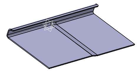
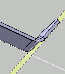
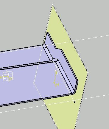
- Be careful when creating a surfacic flange on a joggled web. Indeed,
doing so is impossible when the resulting base feature (i.e. the joggled
web) does not intersect with the surfacic flange support anymore, as is
the case in the example below:
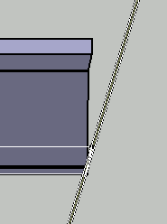
Web as offset by the joggle - view 1
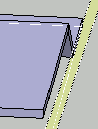
Web as offset by the joggle - view 2
You can ensure that creating a surfacic flange will be possible by using one of the following methodologies:
- either extrapolate the web beyond the support surface so that the joggled web intersects with the support.
- or select the surfacic flange's support surface as the web boundary. You can then create the joggle on web and finally the surfacic flange.
- You cannot create twin joggles having runout directions facing each
other. It could generate a topological inconsistency in case the joggles
have a different depth as shown below.

To simulate a twin joggle in this example, you should create a plane corresponding to the start of the joggle and invert the runout direction as shown below.
Creating a joggle by selecting an offset surface
-
Click Joggle
 .
The Joggle definition dialog box is displayed.
-
Select Surfacic flange 1 as the support and select the yz plane as the joggle plane.
-
Click Surface in the Offset type field and select Symmetry1 in the Offset surface field.

Note that the Joggle Depth Direction arrow is not visible, as this direction is automatically computed according to the relative orientation of the previous support surface. -
Click OK. The joggle (identified as Joggle.1) is created and the specification tree is updated accordingly.
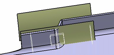
-
Click Joggle
 again. The Joggle definition dialog box is displayed.
 -
Select Plane1 as the joggle plane and click OK.
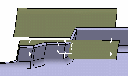
Note that Joggle.2 is computed with the Offset Surface of Joggle.1 as reference.
-
Double-click Joggle.1 on the specification tree. The Joggle definition dialog box is displayed.
-
Click in the Offset surface field and select Extrude.2.
-
Click OK.
Note that Joggle.2 has automatically taken this new surface as reference. If you swap the Offset type of Joggle.1 from surface to depth, the reference is reset to the Surfacic Flange Support Surface. 
You can create several Joggles on the same Offset surface. 
You cannot apply side and joggle compensations when an input surface is selected to define the Offset surface of a Joggle.
Using a Runout Joggle Formula
A Runout Joggle Formula is the mathematical relation between the Depth and the Runout parameters of the Joggle feature.
-
Click Sheet Metal Parameters
 and select the Joggles tab.
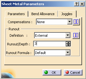
-
Select Design table in the Runout Formula field. A dialog box is displayed.
-
Click Yes and select the Runout_joggle_formula.xls file you previously saved.


-
Column A : Name of the formula which will appear in the Formula field of the Joggle panel.
-
Column B, C, D : Formula coefficients
-
A Literal of type Length is created if there is a length unit. If not, the created Literal is of type Real
-
The number of coefficient columns is free
-
-
Column E : Formula body in which you can use the following keywords that will be automatically replaced by the corresponding parameter value:
-
THICKNESS, defined on the Sheetmetal Parameters,
-
DEFAULTBENDRADIUS, defined on the Sheetmetal Parameters,
-
DEPTH, defined on the current Joggle,
-
RUNOUT, defined on the current Joggle,
-
STARTRADIUS, defined on the current Joggle,
-
ENDRADIUS, defined on the current Joggle.
-

Make sure these keywords are written in capital letters. 
The application of a formula can also depend on a condition, if the formula body column is replaced by these 3 columns: - JoggleRunout_Condition (ex : DEPTH > a3)
- JoggleRunoutFormulaBody_Condition
- JoggleRunoutFormulaBody_NotCondition

You can also apply a Formula only if the Base feature of the Joggle corresponds to a pre-defined type. To do so, create a column entitled JoggleRunoutFormula On. The allowed values of this column are "WEB" and "FLANGE".
- If the value of the column is WEB, the Formula applies to Joggles whose Base Feature is the Web.
- If the value of the column is FLANGE, the Formula applies to Joggles whose Base Feature is a Surfacic Flange.
- If the JoggleRunoutFormula On column does not exist, the
Formula applies to any Joggle.

-
-
Click OK.
-
Click Joggle
 .
.You can now choose a formula, taken from the xls file, each one being directly linked to the corresponding row of the design table. 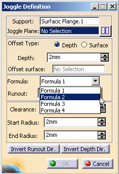
-
Enter the parameters of the Joggle and select the formula.
-
Click OK.
Deactivating Joggles
-
Select Joggle.1 in the specification tree or in the geometry,
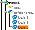
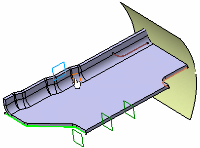
-
In the contextual menu, select Joggle.1 object, then Deactivate.
The joggle is not displayed anymore on the surfacic flange.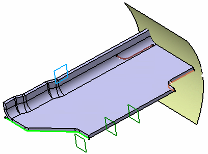

- If you deactivate the surfacic flange on which the joggles have been built, all the joggles are deactivated.
- You can double click on the joggle in the geometry to edit it.
Applying Compensations
Open the Joggle2.CATPart document for a single joggle, Joggle3.CATPart for a twin joggle, and Joggle4.CATPart for a double joggle.
Standard Files must have been previously imported and a method for compensations defined.
- To import Standard Files:
-
Click Sheet Metal Parameters
 .
.
The Sheet Metal Parameters dialog box is displayed.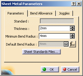
-
Select the Sheet Standards Files... button.
The File Selection window is displayed. -
Select the SheetmetalParametersMethod1.xls file (or the SheetmetalParametersMethod2.xls), available from the samples/DesignTables directory.

Text format files are also available from the samples/DesignTables directory.
-
Define a method for joggle compensation.
- To define a method for the joggle compensation:
-
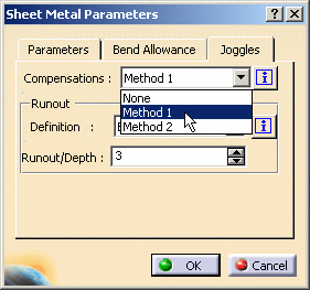
Go to the Joggles tab.
-
In the drop down list of the Compensations field, select Method 1 or Method 2, according to the standard file you previously defined.
-
Click OK to close the Sheet Metal Parameters dialog box.
You are now ready to define compensations. -
Double-click the surfacic flange supporting the joggle to edit it.
-
In the Compensations tab, click the Apply Compensation button.

A joggle compensation cannot be applied : - when the joggle is created while using the Offset surface explicitly,
-
when one of the sides is defined as "None" in the sides and corner tab of the Surfacic Flange Definition dialog box.
On a single joggle
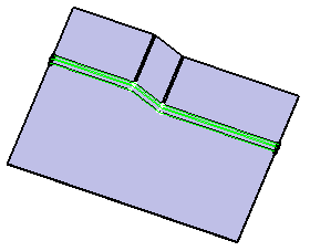 |
| Unfolded single joggle without compensations |
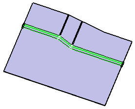 |
| Unfolded single joggle with compensations relying on Method 1 |
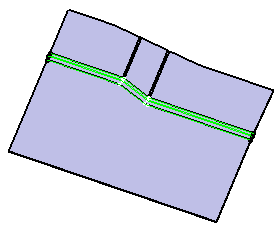 |
| Unfolded single joggle with compensations relying on Method 2 |
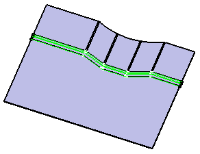
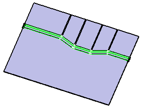
On a twin joggle
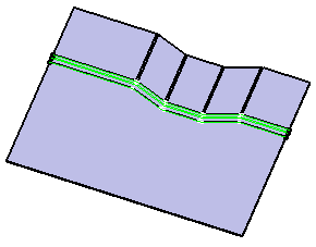 |
| Unfolded twin joggle without compensations |
 |
| Unfolded twin joggle with compensations relying on Method 1 |
 |
| Unfolded twin joggle with compensations relying on Method 2 |
On a double joggle
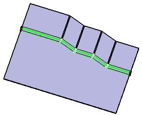 |
| Unfolded double joggle without compensations |
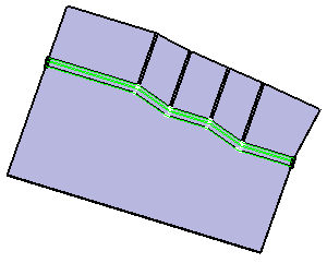 |
| Unfolded double joggle with compensations relying on Method 1 |
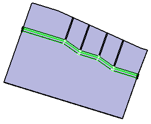 |
| Unfolded double joggle with compensations relying on Method 2 |
![]()
