 |
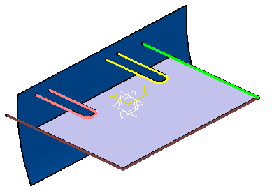
This section explains how to create a web, that
is the main feature of an Aerospace SheetMetal Design part. |
 |
Open the
Web1.CATPart document. |
 |
-
Click Web
 . .
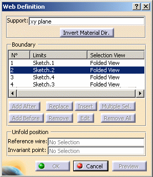
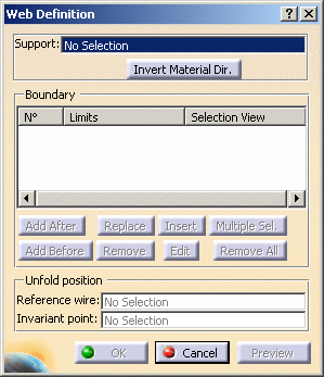
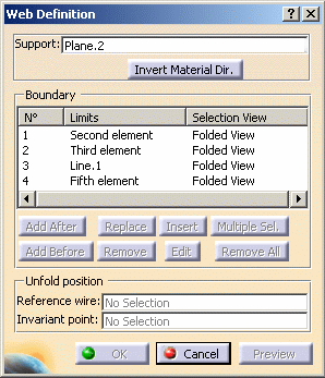
| The Web definition dialog box is displayed. |
| |
 |
| |
-
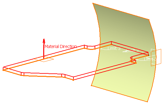
In the Support field, select the support
geometry in the specification tree.
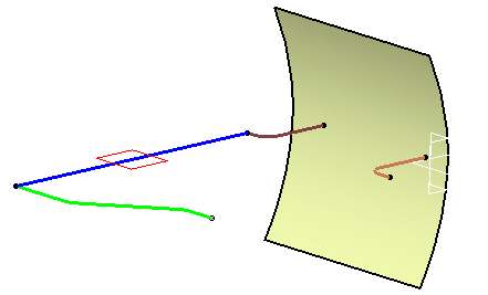 |
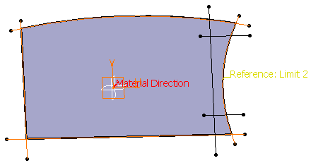
The Material Direction is displayed,
perpendicular to the geometrical support. You can reverse the
direction by clicking the arrow or the Invert Material Dir
button.
|
|
 |
The support can either be a plane, a closed sketch
or a surface. |
-
In the Boundary field, in the case of an open geometry,
select the elements (curves, surfaces, planes or sketches) that limit the support geometry.
 |
The elements must be selected consecutively. |
| |
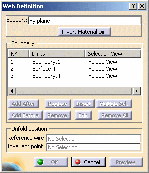
| They are displayed in the Boundary frame as well as
in the 3D geometry, in the order you have just chosen them. |
| |
 |
| |
| When a closed profile can be built, a light preview
of the web is available. Otherwise, click Preview. |
| |
 |
| |
You can modify your boundaries by selecting an
existing limit and using the following buttons to:
-
add a
limit after the selected limit (Add After)
-
add a limit before the
selected limit (Add Before)
-
replace a limit (Replace)
-
remove a limit (Remove)
-
select a limit more
than one time (Insert)
|
| |
 |
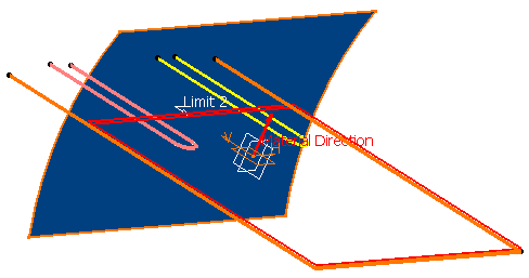
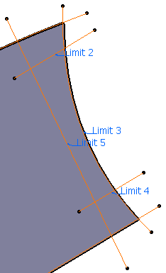
In the following example, we first select three elements to
limit the web.
|
- select several limits or several times the same limit to
modify the existing limit (Multiple Sel). This option
is available once you have selected Add After,
Add Before, Replace: the Limits to Add dialog
box appears to let you select the limits.
|
| |
 |
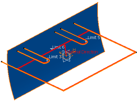
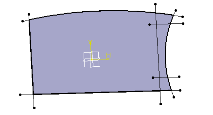
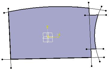
The aim of the following example is to relimit the web so as to
obtain the result as shown below. |
 |
|
 |
|
Web before relimitation |
|
Web after relimitation |
| |
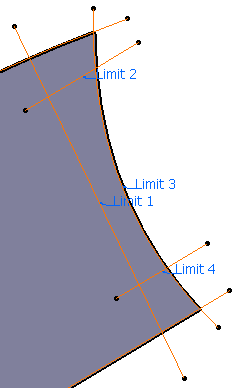
| To do this, you have to select twice
the same limit (vertical line). |
| |
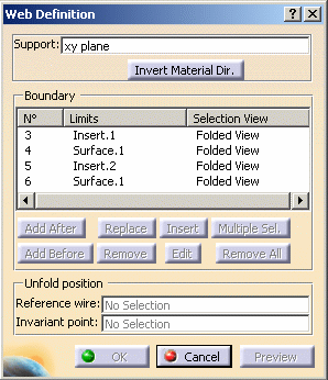
- Select Sketch.2 in the Web definition dialog box,
(also called Limit 2).
- Click on Replace
to define a new limit.
- Click Multiple Sel. to select the
sketches that are to be part of Limit 2.
- In the Replacing Limits dialog box, select each sketch clockwise to define Limit 2.
You have to select sketch.5 (vertical line) twice: it is
considered as Limit 1 then as Limit 5 once selection is over.
|
- remove all limits (Remove All)
|
| |
| Once you have modified the
selection, a light preview is available. You can click the
Preview button to display the result of the web. |
| |
 |
When the profile is defined by a list of
geometrical elements, the following operations are
performed:
|
|
|
|
|
-
Click OK.
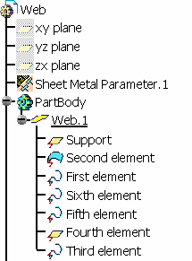
| The web (identified as Web.1) is
created and the specification tree is updated accordingly. |
|
|
|
|
 |
In hybrid context, even though a web is created
with several features, none are aggregated under the web in the
specification tree.
| Yet, if you open a part created in a
previous release, the specification tree will be displayed accordingly to
the previous behavior. For more information about Hybrid Design, refer to
the
Hybrid Design section in the Part Design User's Guide. |
|
|
| |
|
| |
Creating a surfacic web
|
 |
Open the
Web2.CATPart document. |
 |
-
Click Web
 . .
| The Web definition dialog box is displayed. |
| |
 |
-
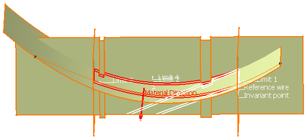
Select Extrude.1 as the support of the web.
-
Select a reference wire and an invariant point as
references for the unfolding of the web.
-
In the Boundary field, select the
elements that limit the support geometry.
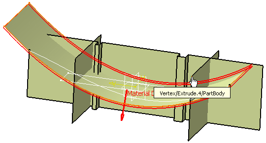
| In our example, we chose Extrude 4,
Project 1, Extrude 2 and Extrude 3 (but you can also
select Sketch 6). |
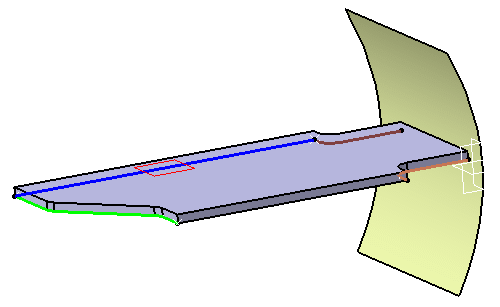
| A preview of the web (in red) and a preview of the
unfolded web (in white) is displayed. |
 |
If the white
preview is not displayed, you have to reconsider the
reference wire or the invariant point. |
 |
 |
The selection of limits is optional if
you want the web to have the same dimensions
and shape than the support. |
 |
While defining the limits of the support
geometry, you can select an extrusion : it
is the intersection between this extrusion
and the web support that will be
considered as the limit. |
-
Click OK.
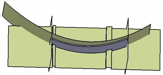
| The web (identified as Web.1) is
created and the specification tree is updated accordingly. |
 |
|
|
 |


