|
|
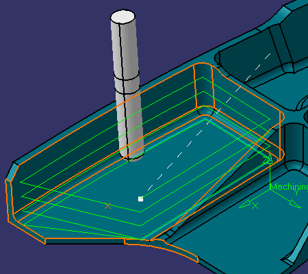
This task illustrates how to create a Multi-Axis Flank Contouring operation in the program. | |
|
|
1. | Select the Multi-Axis Flank
Contouring icon
A Multi-Axis Flank Contouring entity along is added to the program. It is initialized with the tool used in the previous operation.
|
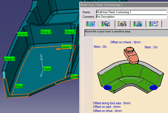
| 2. | Click the red part surface in the icon then select the desired part surface in the 3D window. | |
| 3. | Click the red drive surface in the icon then select the desired drives in the 3D window. | |
| 4. | Click the start and stop elements in the icon then select the desired elements in the 3D window. | |
 |
||
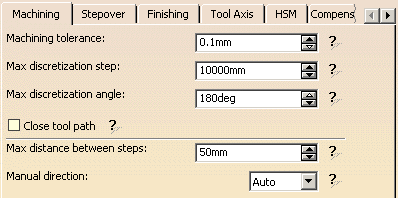
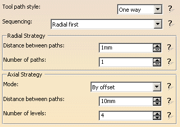
| 5. | Select the Strategy tab
page
|
|
|
||
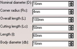
| 6. | Select the Tool tab page
|
|
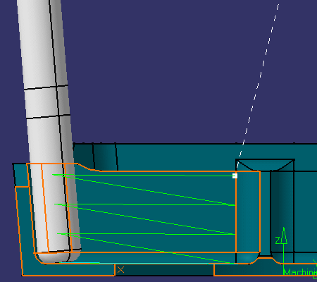
| 7. | Click Replay to compute the operation and
visualize the tool path.
|
|
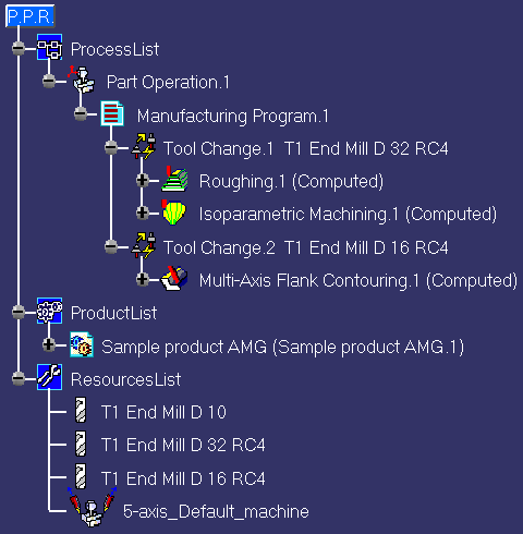
| 8. | Click OK to create the operation. The
specification tree is updated as follows.
|
|
|
|
||
