This task shows you how to create a Translate/Copy element, either within the same product or onto different products.
In this scenario an example with Joint Elements is given, but you can also select a Joint Body or an Assembly Joint.
Open the Translate.CATProduct document.
-
Select the joint element from the specification tree.
-
Select Translates BiW object Copies
 in the Automotive BiW Fasteners toolbar.
By default, the Target parent object is the same as the Source objects, here Joint Body.1. 
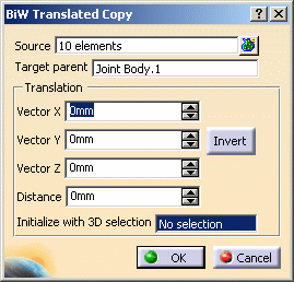
If the source objects and the target parent belong to two different products, you need to explicitly select the target parent in a product different from the source's objects. The BiW Translated Copy dialog box opens. 
-
Select the Translation vectors.
You can either: -
manually select the X, Y, and Z vectors using the spinners, or
-
select a geometrical element to initialize with the selection and provide a direction.
This element can either be a surface or a plane (the normal to this surface or plane is computed to obtain the translation direction), or a line or an edge (the line or edge direction gives the translation direction)
-
-
Define the Distance to specify the length of the translation vector.
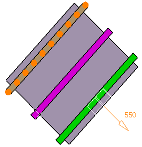
Whenever vector values are modified, the Distance value is automatically updated as the length of the vector, and vice-versa. Therefore the distance value is always equal to the corresponding vector value. In our scenario we defined a distance of 550mm. -
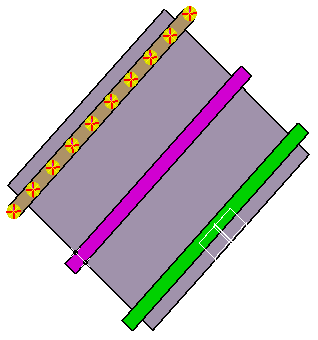
Click the Invert button to reverse the direction vector.

-
Click OK.
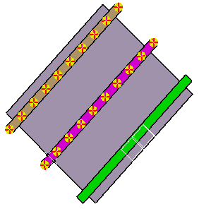
The translated joint elements are created. 
When the naming rule is not active, the copied elements have the same name as the source elements.
![]()
